After my disappointing results from synchronizing PS3 Eyes, I've been discouraged and not working on the vision stuff. However, I have been thinking about the physical robot side of things.
From early experiments with taking aluminum tubes and hacking at them with hand tools, I had come to realize that either my robot was going to be imprecise and ugly, or I was going to need a professional to manufacture the robot's skeleton.
You might have noticed from photos that at some point during my project my wife let me move our outdoor ping pong table indoors, specifically into our unfurnished formal living room. Maybe she would be equally accommodating about a metalworking shop in our house.
No. Something about our baby and metal chips.
I started looking around for machine shops where you could get access to some fancy tools. Those sorts of things must exist, right? If they do, they're not easy to find. I thought about signing up for a college class just to get access to a school's facilities. I looked at expensive hobby CNC milling machines that I could fit in my home office.
Then I found Techshop.
After reading their website, I was sure they would be in San Francisco, where apparently all creative work in the world is done. But the mechanical gods were smiling on me: one of their half-dozen locations is 30 minutes from my house. (They are based in San Francisco, of course.)
I went to visit, did a tour, and signed up on the spot. For $125 a month I get unlimited access to their shop. They even provide classes on how to use the equipment, which is absolutely necessary for me. The "catch", as they put it, is that the classes are mandatory before your unlimited access to each machine is opened, otherwise their insurance won't cover you losing your fingers. The classes also cost money, but what's money when you're building a robot that will revolutionize a game that nobody takes seriously?
So far I've taken six classes. I can use the metal shop, except the metal lathe and the "Ironworker" plate masher thing. I can use the wood lathe, but not the rest of the wood shop. I can use the 3D printer. I also have access to some marvellous design software: Autodesk Inventor. I'm scheduled to learn how to use the Ironworker and a laser cutter later this week, and I plan to learn how to use the Tormach CNC milling machine next week. Perhaps the coolest machine is a Flow water jet cutter that can cut through 8 inches of steel or perforate a kleenex, depending on your needs.
My wife has been very accommodating about Techshop. I've been disappearing a lot to take classes. I have been bringing back my class projects as gifts, so I'm sure that has helped. She now proudly displays my sheet metal box, my bottle opener, and my business card stand. (Actual truth: she said the business card stand is the only one that doesn't look like a 5 year old made it. The bottle opener doesn't even work.)
My hope is that I will take more classes, learn more about what is possible, then design my robot using Inventor and machine it with great skill. I expect to use a lot of CNC, rather than actual skill with my hands. But for now, I haven't actually done anything about the robot.
If you live near a Techshop, and are at all interested in making stuff, I highly recommend you check them out. If you want to join, drop me a comment and we both can benefit from free classes in their refer-a-friend program.
Monday, May 13, 2013
Synchronizing PS3 Eyes
After taking a very carefully constructed video, with lots of landmark points and excellent lighting, I realized that I still don't have what I need to complete the triangulation. Not only are my two cameras not synchronized -- meaning taking their video frames at the same time -- but I also have no way to tell what the offset between the frames is. I had been working under the assumption that I could find that offset, and use that to interpolate ball locations in the images between two frames, to arrive at a synchronized left/right location.
Time Offset From Ball Bounces
I tried to use the event of the ball bouncing to determine the time offset. If you look at the three frames surrounding a bounce, you can approximate when the ball bounced to sub-frame accuracy. For example, say the ball fell 2 pixels between the first and second frames, and then rose 4 pixels between the second and third frames. Since the frames are evenly spaced in time, if we assume the ball has a constant velocity, the actual distance travelled in each of those intervals must be the same. We can conclude that the ball must have bounced in the first interval, and that it travelled 4 pixels in each interval. To have travelled 4 pixels in the first interval, including a bounce, yet only have a net downward move of 2 pixels, it must have dropped 3, then rose 1. The bounce was after 3/4ths of the distance, and so happened after 3/4ths of the time interval between frames.
When doing that on a video, I expected to be able to find the offset between the cameras in a number of bounces, and use the average. What I found was that the offset kept changing. In fact, it kept drifting, always getting larger. I've decided this means that the cameras don't actually have the same frame rate, even though they are nominally supposed to be 125 fps. Without the same frame rate, I can't just determine the offset once, and thereafter know how to interpolate.
Hardware Sync
This brought me back to hardware synchronization of the cameras. I have mentioned this as a possibility in the past, but I shied away from it because it sounded difficult to execute. It sounded more likely to cause my camera to burst into flames than to synchronize it. But I was running out of options, so I've pursued this avenue.
The concept sounds good. Some engineering students found that the chips in the cameras are designed to accept external triggers for take frames of a video. Sony has not used this capability because it didn't fit their application. But the chip can still do it. These students, through trial and error, found where the frame trigger from the chip was wired on Sony's board. (This frame trigger is apparently called FSIN, so I'll be calling it that to sound smarter.) On Sony's PCB, FSIN is just a dead end. It doesn't go anywhere. But it is exposed.
These students wired the FSIN on one camera to the VSYNC on another camera. VSYNC is apparently an output signal from the chip when it starts taking a snapshot, and FSIN is the input that causes a camera to take a snapshot. So by connecting them, these students made a master/slave setup, where every time the master camera took a picture, the slave would also take one.
Here is a picture of FSIN and VSYNC on the PCB. There is a wire soldered onto FSIN. (This is not my picture. I believe it was taken by the engineering students.)
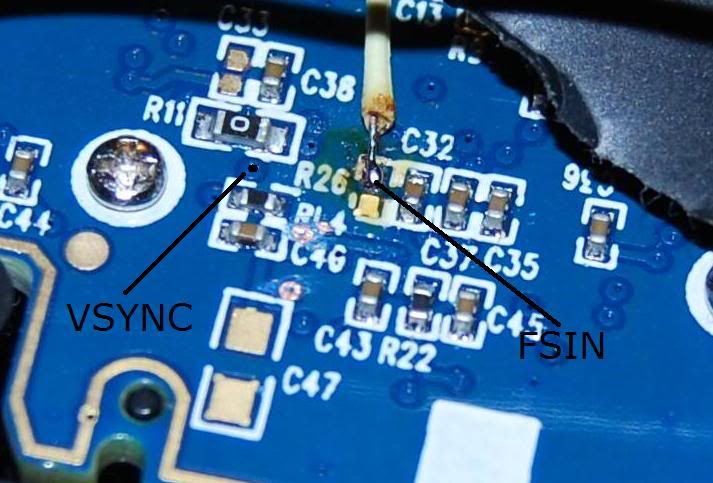
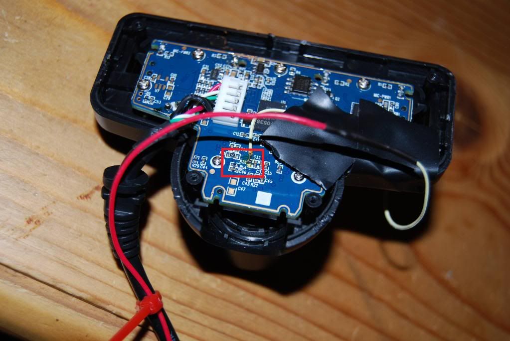
What you can't tell from this picture is how damn small those pieces are. I think this image is about 2cm across. This next picture shows the whole back of the camera.
Do you remember how I told you about my weak soldering skills? Do you remember those ugly joints on the Dynamixel power cord? Right...
Diving In To Electronics
Well, long story short, despite all the evidence that I was going to ruin my camera, I went for it.
I cracked open the camera (literally... it has some one-time plastic snaps holding it together and I had to pry at them until they gave up), unscrewed some stuff, and removed the PCB. Here are video and picture instructions that I found on the process. I got out my trusty $7 soldering iron, a "helping hands" thingy with a magnifying glass, and some bits of wire.
In the end, I did get a wire attached to FSIN on both of my cameras. Somehow I managed to avoid attaching it to the resistor next to FSIN. Somehow I managed to avoid frying any components. On one camera I did pull the little copper contact for FSIN right off of the board... but flooding the exposed depression where the contact pad used to be with solder seemed to reconnect to the invisible wires in the PCB, so it doesn't seem to have mattered. Like the images above, I've used electrical tape to secure the wire to the camera, because a little tug could rip it off (that's how the contact pad was removed the first time). I've been more cautious than these students, as I've wrapped the wire around the case and taped in three places. Now there are lots of shock absorbers that will give before I break the solder connection.
I rebuilt the cameras to the point where they have a nice tilting stand under them again. I left the back panel off so that the wires can escape. In theory I could dremel a little notch in the plastic back to feed the wire through, but I haven't bothered. I had to solder a long wire to the itty-bitty FSIN wire so that it could reach any significant distance. I used speaker wire, since that's what I have long lengths of. Thankfully soldering two wires together isn't that hard. I even put a shrink-wrap cover on them so they look very professional.
Triggering FSIN
Having a wire attached to FSIN doesn't actually accomplish anything unless I can send a signal over the wire. To do that, I returned to Arduino. I told you that thing would come in handy one day.
The FSIN input is apparently a rising-edge triggered signal at 3.3V (all this according to the engineering students referenced above or other online sources). I set up both the left and right camera speaker wire to the same digital output pin on the Arduino. I programmed it to send a square wave on that pin, alternating 0V and 3.3V every 4000us (that's 250 times per second, i.e. double 125 fps). Whenever it goes from 0V to 3.3V it should be triggering a frame capture.
Measuring Frame Rate
When I turned it on I realized that I had no easy way to tell if it was working. So I came up with a wickedly clever plan to test the timing of the camera frames.
I have some small red LED lights in my electronics junk box that have a very fast switching speed, meaning they can turn on and off very fast. Faster than the frame rate of the cameras. In fact, I've found that turning them on and off can be done in under 1000us. Probably much under 1000us, but I don't know for sure. (Note: not all LEDs are fast at turning off. I have another batch of larger LEDs and they would glow for a much longer period of time after the power was removed, making them not useful for my purposes.)
My plan is to flash lights at a high speed, and compare the frames from the two cameras to see if they were both seeing the same step in the light sequence. If so, they would be synchronized (at least within 1000us). I arranged 8 lights in a breadboard that would each turn on, one-at-a-time, for 1000us, then off again, so only one light would be on at a time. Every 8000us (125 times per second) the pattern would repeat. In addition I added more LEDs that would count the number of 8000us cycles in binary. The count should increment once per frame, so you could also call it a frame counter.
All the LEDs were hooked up to my Arduino on digital pins. I am now thankful that I bought the larger Arduino even though I had no plan to use all those connections at the time. I programmed the Arduino to carry out the pattern I just described. With the human eye, the pattern is too fast to see. The 8 sequential LEDs appear to be in a steady half-on state (half-on is interesting because they are only on 1/8th of the time; I suspect that's my brain messing with me). The lower bits of the binary counter also appear steady, perhaps at 3/4 brightness. As you get to the 4-bit of the counter, the switching becomes visible. To test that I had the pattern right, I slowed it down significantly until I could see all the lights operating. Yep, I got it right.
Next I pointed a single camera at the LED array on my desk. Because of the bad lighting, I had to put a 100W incandescent bulb inches above the LEDs to illuminate the scene sufficiently. (Incandescent lamps are rare in my house. I had to steal my wife's make-up light, which led to many days of arguments about the relative merits of make-up and robot hobbies.)
I added a switch to my growing electronics prototype to enable/disable the LED display and another switch to enable/disable the FSIN signal. I started with FSIN disabled and recorded some video of the LEDs.
Something very cool emerged from the 8 sequential LEDs. At first only one of the 8 LEDs was illuminated in the video. That verifies that my LEDs are switching on and off sufficiently fast. It also means that the frame exposure time is under 1000us. But, as I watched the video, which LED was lit gradually shifted over time. For instance, maybe the 3rd LED was lit at first. It would stay lit in every frame for a while, meaning that the frame was being captured in the same 1000us window within the larger 8000us cycle. But, after maybe 1/2 a second, the 3rd light would get dimmer and the 4th light would start to get brighter. After a full second, the 3rd light would be completely dark and the 4th light would be bright. This movement continued through all 8 LEDs, moving from LED to LED approximately once a second.
So what does that mean? I believe that this is proof that my cameras are not actually operating at precisely 125fps. If the Arduino timer is accurate enough (and I've found discussion online that it is), those lights are repeating 125 times per second "exactly". If the camera was also cycling exactly 125 time per second, then the movement from LED to LED wouldn't happen. Doing some rough math, the camera was losing 1000us (the difference between neighboring LEDs) every 1 second (the approximate time it took for one LED to give way to its neighbor). That's 1 part in 1000 slower than 125 fps, so about 0.125 frames per second is being lost, so the camera is actually working at about 124.875 fps. I know it is slower rather than faster because of the direction the LEDs movement was going. If the 3rd LED gave way to the 2nd, the camera would have been going faster. But it wasn't, it was going slower.
While I know this is some pretty amazing research, it gets better. Stay strapped in.
When I switch on the FSIN signal the pattern changes. Instantly, which LED is lit jumps to the 6th LED, regardless of where it was then I switched it on. Maybe the 7th LED is also lit a little bit, so I'm going to say it's at the 6.25 increment in the 8 light cycle. What's more, there is no longer any drift. That 6th LED will stay lit forever, in every frame.
To me, this means that my FSIN signal is working. It is forcing the camera to take its frames at an exact 125 fps tempo, instead of its inaccurate 124.875 fps. Most importantly, the FSIN signal is working to adjust the camera's timing, which would suggest that sending FSIN to both cameras would cause them to be synchronized.
The way I programmed the Arduino, the FSIN signal is sent at the same time that the 1st LED is turned on. That means that the 6th light is lit 5000us after sending the FSIN signal. To me that indicates that there is a 5000us delay in the electronics from the rising edge of FSIN to the actual frame capture. It's possible that this delay is variable based on other camera settings, but I consistently got this value of around 5000us.
[I would like to get a video of this happening. It would require reassembling my LED array, which was reorganized later and no longer works this way.]
Two Camera Frame Rate Testing
Next, I used both cameras at the same time on my desk. Without FSIN, both cameras showed the movement along the 8 LED loop. They didn't drift at the same speed: the second camera showed slightly slower (or faster, I can't remember) movement, and so its actual frame rate was slightly different (and still not 125 fps). This also means that they didn't see the same LED as being lit. The first camera might see LED 3 at the same time that the second camera sees LED 8.
When FSIN was turned on, both cameras immediately saw the 6th LED lit and the drift stopped. Since they both saw the 6th LED lit, the delay between FSIN and the frame was relatively constant between cameras, which is helpful if I am trying to synchronize them. If I turned off FSIN again, the drift resumed, starting from the 6th LED, then the 7th, etc. The different drift speeds meant that over time (roughly tens of seconds) the two cameras would again be seeing different LEDs lit.
Meanwhile, at the ping pong table...
With this success, I returned to the ping pong table. I set up my cameras, my table, blocked out glare from windows, put in my favorite landmarks. This time I also added my LED array. The LEDs were too close together, so I remade my prototype to spread them out, otherwise two LEDs would appear in the same pixel.
This is when things started to go wrong. The new video with FSIN wasn't synchronized. What? Why? How?
I believe that the problem is with lighting. That 100W bulb was needed to illuminate my desk. Once back on the table, I didn't have lights that are equivalently bright. I even have to darken the room somewhat by blocking sunlight that would create glare on the table. I think this causes the required exposure time to exceed the 8000us frame rate.
When it was on my desk, the exposure time was under 1000us because only one of the 8 LEDs was lit in the pictures. Now that they are on the table, they do not behave the same way. More than one is illuminated at a time. To a rough approximation, they are all lit. Even the binary frame counter becomes ambiguous at times -- i.e. it's hard to tell if a light is on or off. Basically the long exposure is smudging the LED status, ruining the crisp results I had been achieving on my desk.
I don't know how the FSIN signal interacts with the camera's natural timing. And I don't know how the exposure time interacts with both of these things. In theory the Linux driver should be able to control exposure time, but in practice I don't believe it works. I believe that the camera is deciding its own exposure time no matter what I tell it to do.
It wouldn't be the end of the world if I had a long exposure time and my LEDs no longer allowed me to see how well it was working. As long as the cameras stay synchronized, I don't think a long exposure time is that big of a deal -- I'd already been taking videos in these lighting conditions and was happy with them. But somehow the (suspected) long exposure time was also messing with the synchronization. Using the ball-bounce method discussed at the top of this post, the two cameras were not synchronized. The FSIN triggers were not interacting well with a long exposure time.
Bottom line, not only could the LEDs not do the job of measuring the frame rate accurately, but the synchronization that had worked so well on my desk was lost.
What Now?
It's been a long time since my last post. Maybe you noticed. I actually did these experiments over maybe 4 weeks, which is why this post is so long (and I left out some details here and there). I have since done nothing for a number of weeks. I am discouraged again, and don't know what to do next.
I think that if I want to make progress, I might have to buy the expensive cameras that I had been considering originally. Maybe a $22 PS3 Eye is insufficient for the level of detail I need to capture. An expensive camera with a big lens on it should capture more light, and therefore allow short exposures again. The expensive cameras also come designed to take an external trigger signal, so I shouldn't have to hack them to make them work.
Of course, now that I've been discouraged for a while, it gets harder to justify spending a stack of cash...
Time Offset From Ball Bounces
I tried to use the event of the ball bouncing to determine the time offset. If you look at the three frames surrounding a bounce, you can approximate when the ball bounced to sub-frame accuracy. For example, say the ball fell 2 pixels between the first and second frames, and then rose 4 pixels between the second and third frames. Since the frames are evenly spaced in time, if we assume the ball has a constant velocity, the actual distance travelled in each of those intervals must be the same. We can conclude that the ball must have bounced in the first interval, and that it travelled 4 pixels in each interval. To have travelled 4 pixels in the first interval, including a bounce, yet only have a net downward move of 2 pixels, it must have dropped 3, then rose 1. The bounce was after 3/4ths of the distance, and so happened after 3/4ths of the time interval between frames.
When doing that on a video, I expected to be able to find the offset between the cameras in a number of bounces, and use the average. What I found was that the offset kept changing. In fact, it kept drifting, always getting larger. I've decided this means that the cameras don't actually have the same frame rate, even though they are nominally supposed to be 125 fps. Without the same frame rate, I can't just determine the offset once, and thereafter know how to interpolate.
Hardware Sync
This brought me back to hardware synchronization of the cameras. I have mentioned this as a possibility in the past, but I shied away from it because it sounded difficult to execute. It sounded more likely to cause my camera to burst into flames than to synchronize it. But I was running out of options, so I've pursued this avenue.
The concept sounds good. Some engineering students found that the chips in the cameras are designed to accept external triggers for take frames of a video. Sony has not used this capability because it didn't fit their application. But the chip can still do it. These students, through trial and error, found where the frame trigger from the chip was wired on Sony's board. (This frame trigger is apparently called FSIN, so I'll be calling it that to sound smarter.) On Sony's PCB, FSIN is just a dead end. It doesn't go anywhere. But it is exposed.
These students wired the FSIN on one camera to the VSYNC on another camera. VSYNC is apparently an output signal from the chip when it starts taking a snapshot, and FSIN is the input that causes a camera to take a snapshot. So by connecting them, these students made a master/slave setup, where every time the master camera took a picture, the slave would also take one.
Here is a picture of FSIN and VSYNC on the PCB. There is a wire soldered onto FSIN. (This is not my picture. I believe it was taken by the engineering students.)
What you can't tell from this picture is how damn small those pieces are. I think this image is about 2cm across. This next picture shows the whole back of the camera.
Do you remember how I told you about my weak soldering skills? Do you remember those ugly joints on the Dynamixel power cord? Right...
Diving In To Electronics
Well, long story short, despite all the evidence that I was going to ruin my camera, I went for it.
I cracked open the camera (literally... it has some one-time plastic snaps holding it together and I had to pry at them until they gave up), unscrewed some stuff, and removed the PCB. Here are video and picture instructions that I found on the process. I got out my trusty $7 soldering iron, a "helping hands" thingy with a magnifying glass, and some bits of wire.
In the end, I did get a wire attached to FSIN on both of my cameras. Somehow I managed to avoid attaching it to the resistor next to FSIN. Somehow I managed to avoid frying any components. On one camera I did pull the little copper contact for FSIN right off of the board... but flooding the exposed depression where the contact pad used to be with solder seemed to reconnect to the invisible wires in the PCB, so it doesn't seem to have mattered. Like the images above, I've used electrical tape to secure the wire to the camera, because a little tug could rip it off (that's how the contact pad was removed the first time). I've been more cautious than these students, as I've wrapped the wire around the case and taped in three places. Now there are lots of shock absorbers that will give before I break the solder connection.
I rebuilt the cameras to the point where they have a nice tilting stand under them again. I left the back panel off so that the wires can escape. In theory I could dremel a little notch in the plastic back to feed the wire through, but I haven't bothered. I had to solder a long wire to the itty-bitty FSIN wire so that it could reach any significant distance. I used speaker wire, since that's what I have long lengths of. Thankfully soldering two wires together isn't that hard. I even put a shrink-wrap cover on them so they look very professional.
Triggering FSIN
Having a wire attached to FSIN doesn't actually accomplish anything unless I can send a signal over the wire. To do that, I returned to Arduino. I told you that thing would come in handy one day.
The FSIN input is apparently a rising-edge triggered signal at 3.3V (all this according to the engineering students referenced above or other online sources). I set up both the left and right camera speaker wire to the same digital output pin on the Arduino. I programmed it to send a square wave on that pin, alternating 0V and 3.3V every 4000us (that's 250 times per second, i.e. double 125 fps). Whenever it goes from 0V to 3.3V it should be triggering a frame capture.
Measuring Frame Rate
When I turned it on I realized that I had no easy way to tell if it was working. So I came up with a wickedly clever plan to test the timing of the camera frames.
I have some small red LED lights in my electronics junk box that have a very fast switching speed, meaning they can turn on and off very fast. Faster than the frame rate of the cameras. In fact, I've found that turning them on and off can be done in under 1000us. Probably much under 1000us, but I don't know for sure. (Note: not all LEDs are fast at turning off. I have another batch of larger LEDs and they would glow for a much longer period of time after the power was removed, making them not useful for my purposes.)
My plan is to flash lights at a high speed, and compare the frames from the two cameras to see if they were both seeing the same step in the light sequence. If so, they would be synchronized (at least within 1000us). I arranged 8 lights in a breadboard that would each turn on, one-at-a-time, for 1000us, then off again, so only one light would be on at a time. Every 8000us (125 times per second) the pattern would repeat. In addition I added more LEDs that would count the number of 8000us cycles in binary. The count should increment once per frame, so you could also call it a frame counter.
All the LEDs were hooked up to my Arduino on digital pins. I am now thankful that I bought the larger Arduino even though I had no plan to use all those connections at the time. I programmed the Arduino to carry out the pattern I just described. With the human eye, the pattern is too fast to see. The 8 sequential LEDs appear to be in a steady half-on state (half-on is interesting because they are only on 1/8th of the time; I suspect that's my brain messing with me). The lower bits of the binary counter also appear steady, perhaps at 3/4 brightness. As you get to the 4-bit of the counter, the switching becomes visible. To test that I had the pattern right, I slowed it down significantly until I could see all the lights operating. Yep, I got it right.
Next I pointed a single camera at the LED array on my desk. Because of the bad lighting, I had to put a 100W incandescent bulb inches above the LEDs to illuminate the scene sufficiently. (Incandescent lamps are rare in my house. I had to steal my wife's make-up light, which led to many days of arguments about the relative merits of make-up and robot hobbies.)
I added a switch to my growing electronics prototype to enable/disable the LED display and another switch to enable/disable the FSIN signal. I started with FSIN disabled and recorded some video of the LEDs.
Something very cool emerged from the 8 sequential LEDs. At first only one of the 8 LEDs was illuminated in the video. That verifies that my LEDs are switching on and off sufficiently fast. It also means that the frame exposure time is under 1000us. But, as I watched the video, which LED was lit gradually shifted over time. For instance, maybe the 3rd LED was lit at first. It would stay lit in every frame for a while, meaning that the frame was being captured in the same 1000us window within the larger 8000us cycle. But, after maybe 1/2 a second, the 3rd light would get dimmer and the 4th light would start to get brighter. After a full second, the 3rd light would be completely dark and the 4th light would be bright. This movement continued through all 8 LEDs, moving from LED to LED approximately once a second.
So what does that mean? I believe that this is proof that my cameras are not actually operating at precisely 125fps. If the Arduino timer is accurate enough (and I've found discussion online that it is), those lights are repeating 125 times per second "exactly". If the camera was also cycling exactly 125 time per second, then the movement from LED to LED wouldn't happen. Doing some rough math, the camera was losing 1000us (the difference between neighboring LEDs) every 1 second (the approximate time it took for one LED to give way to its neighbor). That's 1 part in 1000 slower than 125 fps, so about 0.125 frames per second is being lost, so the camera is actually working at about 124.875 fps. I know it is slower rather than faster because of the direction the LEDs movement was going. If the 3rd LED gave way to the 2nd, the camera would have been going faster. But it wasn't, it was going slower.
While I know this is some pretty amazing research, it gets better. Stay strapped in.
When I switch on the FSIN signal the pattern changes. Instantly, which LED is lit jumps to the 6th LED, regardless of where it was then I switched it on. Maybe the 7th LED is also lit a little bit, so I'm going to say it's at the 6.25 increment in the 8 light cycle. What's more, there is no longer any drift. That 6th LED will stay lit forever, in every frame.
To me, this means that my FSIN signal is working. It is forcing the camera to take its frames at an exact 125 fps tempo, instead of its inaccurate 124.875 fps. Most importantly, the FSIN signal is working to adjust the camera's timing, which would suggest that sending FSIN to both cameras would cause them to be synchronized.
The way I programmed the Arduino, the FSIN signal is sent at the same time that the 1st LED is turned on. That means that the 6th light is lit 5000us after sending the FSIN signal. To me that indicates that there is a 5000us delay in the electronics from the rising edge of FSIN to the actual frame capture. It's possible that this delay is variable based on other camera settings, but I consistently got this value of around 5000us.
[I would like to get a video of this happening. It would require reassembling my LED array, which was reorganized later and no longer works this way.]
Two Camera Frame Rate Testing
Next, I used both cameras at the same time on my desk. Without FSIN, both cameras showed the movement along the 8 LED loop. They didn't drift at the same speed: the second camera showed slightly slower (or faster, I can't remember) movement, and so its actual frame rate was slightly different (and still not 125 fps). This also means that they didn't see the same LED as being lit. The first camera might see LED 3 at the same time that the second camera sees LED 8.
When FSIN was turned on, both cameras immediately saw the 6th LED lit and the drift stopped. Since they both saw the 6th LED lit, the delay between FSIN and the frame was relatively constant between cameras, which is helpful if I am trying to synchronize them. If I turned off FSIN again, the drift resumed, starting from the 6th LED, then the 7th, etc. The different drift speeds meant that over time (roughly tens of seconds) the two cameras would again be seeing different LEDs lit.
Meanwhile, at the ping pong table...
With this success, I returned to the ping pong table. I set up my cameras, my table, blocked out glare from windows, put in my favorite landmarks. This time I also added my LED array. The LEDs were too close together, so I remade my prototype to spread them out, otherwise two LEDs would appear in the same pixel.
This is when things started to go wrong. The new video with FSIN wasn't synchronized. What? Why? How?
I believe that the problem is with lighting. That 100W bulb was needed to illuminate my desk. Once back on the table, I didn't have lights that are equivalently bright. I even have to darken the room somewhat by blocking sunlight that would create glare on the table. I think this causes the required exposure time to exceed the 8000us frame rate.
When it was on my desk, the exposure time was under 1000us because only one of the 8 LEDs was lit in the pictures. Now that they are on the table, they do not behave the same way. More than one is illuminated at a time. To a rough approximation, they are all lit. Even the binary frame counter becomes ambiguous at times -- i.e. it's hard to tell if a light is on or off. Basically the long exposure is smudging the LED status, ruining the crisp results I had been achieving on my desk.
I don't know how the FSIN signal interacts with the camera's natural timing. And I don't know how the exposure time interacts with both of these things. In theory the Linux driver should be able to control exposure time, but in practice I don't believe it works. I believe that the camera is deciding its own exposure time no matter what I tell it to do.
It wouldn't be the end of the world if I had a long exposure time and my LEDs no longer allowed me to see how well it was working. As long as the cameras stay synchronized, I don't think a long exposure time is that big of a deal -- I'd already been taking videos in these lighting conditions and was happy with them. But somehow the (suspected) long exposure time was also messing with the synchronization. Using the ball-bounce method discussed at the top of this post, the two cameras were not synchronized. The FSIN triggers were not interacting well with a long exposure time.
Bottom line, not only could the LEDs not do the job of measuring the frame rate accurately, but the synchronization that had worked so well on my desk was lost.
What Now?
It's been a long time since my last post. Maybe you noticed. I actually did these experiments over maybe 4 weeks, which is why this post is so long (and I left out some details here and there). I have since done nothing for a number of weeks. I am discouraged again, and don't know what to do next.
I think that if I want to make progress, I might have to buy the expensive cameras that I had been considering originally. Maybe a $22 PS3 Eye is insufficient for the level of detail I need to capture. An expensive camera with a big lens on it should capture more light, and therefore allow short exposures again. The expensive cameras also come designed to take an external trigger signal, so I shouldn't have to hack them to make them work.
Of course, now that I've been discouraged for a while, it gets harder to justify spending a stack of cash...
Monday, April 8, 2013
Barriers to triangulation in video
I've been doing a little work, here and there. I figure it's time to provide an update, even without reaching the milestones I was pursuing.
New Landmarks
I created a new table setup with new landmarks, with an emphasis on the area over the table. Mr. W suggested that using the legs under the table was not helping, because it's the area over the table that we need to be accurate with. And panning the camera down to see the legs was removing our view of the playing area above the table. Both good observations.
So now I have lots of points over the table. I used some more objects from around the house, and either rested them on the table, or stood them up along the sides of the table. Most importantly, I am making use of the other half of the table to provide a backdrop with interesting features that I can measure. Here is the left image of the new landmarks, with the points marked.

I was hoping that using the setup would improve my reprojection error. In a previous post, I believe I said that I had the reprojection error down to 1.5cm or something like that. I now think I was mistaken. It was more like 3.5cm when using cameras far apart, which ought to have triangulation advantages.
Unfortunately, my reprojection error is not better. I'm now getting about 4cm average error, which is fairly significant. Knowing the ball's location to within 4cm is not that reassuring.
The first possible explanation is the inherent bad resolution of the images. I'm only marking landmarks to the nearest pixel. Many of the new landmarks are further away from the cameras, meaning that a single pixel covers more space.
The second possible explanation is that my real-world measurements might not be accurate enough. Some of these new landmarks are not as easy to measure. For example, for the vertical cardboard boxes, I was able to accurately measure the bottom, outside, near corner of the box, and then measure the height and width of the box. In a perfect world that would locate the landmark at the top well. In an imperfect world, the box may be leaning one way or the other. The vertical metal posts jutting up from the floor along the edge of the table might not be perfectly vertical. They might be leaning in or out, forward or back.
My best idea to overcome these problems is to run a numerical optimization to adjust the x,y locations that I've selected to subpixel accuracy, and even adjust the x,y,z locations of the uncertain landmarks (i.e. the table corners are exact by definition, but others are error-prone measurements). That's a fair bit of effort, and would make use of a non-free library that I use for work... meaning my code would no longer be open source and shareable.
Video Sync
The next big problem I encountered is the sync of the left and right cameras. As I've said before, I need to know how far apart the left and the right images are in time so that I can attempt to interpolate points before doing triangulation. Last time I wrote about this, I didn't know how I was going to solve it, so I was briefly quite happy when I found that OpenCV will provide a timestamp for each frame as you read a video file, using the VideoCapture::get(CV_CAP_PROP_POS_MSEC) method.
My joy was short-lived, however, when I found that the timestamps don't seem to be accurate. The timestamps are milliseconds since video start, not an absolute time, so the offset of the starting times of the two videos needs to be found. I was trying to calculate the offset by identifying the frames/timestamps before and after six ball bounces in the videos. The ball bouncing is an easy event to use to synchronize on. Unfortunately the offset at each of those six ball bounces was different, drifting over time. It started as 1403ms and ended as 1475ms.
I think the timestamps are simply applying the average frame rate to calculate the time, rather than actually measuring time, and that the actual frame rate isn't steady enough to be using the average frame rate for this purpose. Said another way, I think OpenCV assumes the frames are evenly spaced in time, but in reality there is jitter in the frame rate. This would mean that the timestamps are essentially useless for synchronizing.
Triangulation
I have manually marked the x,y locations of the ball in a few seconds of each camera's video. When using my wonderful ball-marking tool that still takes many minutes per second of video. Now I don't know what to do with them, because I don't know how to correlate the two cameras together. I need to know the x,y locations of the ball in both cameras at the same instant in order to do a triangulation. Mr. W has been proposing to interpolate one camera's ball positions in consecutive frames to approximate the location at the same instant as a frame from the other camera, but that requires at least being able to choose the nearest frame from the other video (and really needs even more precision to do the interpolation).
Even if I solve that problem, my triangulation will still be 4cm off of the true location.
So that's where things are at the moment. I'm not sure what's going to happen next. I might explore the live video capabilities of OpenCV to see if I can synchronize better that way. (Recall that I am currently using guvcview to record videos, then replaying them with OpenCV.) Maybe I can get timestamps more accurately that way, though it would make it very hard to do research work if I need to do everything live.
New Landmarks
I created a new table setup with new landmarks, with an emphasis on the area over the table. Mr. W suggested that using the legs under the table was not helping, because it's the area over the table that we need to be accurate with. And panning the camera down to see the legs was removing our view of the playing area above the table. Both good observations.
So now I have lots of points over the table. I used some more objects from around the house, and either rested them on the table, or stood them up along the sides of the table. Most importantly, I am making use of the other half of the table to provide a backdrop with interesting features that I can measure. Here is the left image of the new landmarks, with the points marked.
I was hoping that using the setup would improve my reprojection error. In a previous post, I believe I said that I had the reprojection error down to 1.5cm or something like that. I now think I was mistaken. It was more like 3.5cm when using cameras far apart, which ought to have triangulation advantages.
Unfortunately, my reprojection error is not better. I'm now getting about 4cm average error, which is fairly significant. Knowing the ball's location to within 4cm is not that reassuring.
The first possible explanation is the inherent bad resolution of the images. I'm only marking landmarks to the nearest pixel. Many of the new landmarks are further away from the cameras, meaning that a single pixel covers more space.
The second possible explanation is that my real-world measurements might not be accurate enough. Some of these new landmarks are not as easy to measure. For example, for the vertical cardboard boxes, I was able to accurately measure the bottom, outside, near corner of the box, and then measure the height and width of the box. In a perfect world that would locate the landmark at the top well. In an imperfect world, the box may be leaning one way or the other. The vertical metal posts jutting up from the floor along the edge of the table might not be perfectly vertical. They might be leaning in or out, forward or back.
My best idea to overcome these problems is to run a numerical optimization to adjust the x,y locations that I've selected to subpixel accuracy, and even adjust the x,y,z locations of the uncertain landmarks (i.e. the table corners are exact by definition, but others are error-prone measurements). That's a fair bit of effort, and would make use of a non-free library that I use for work... meaning my code would no longer be open source and shareable.
Video Sync
The next big problem I encountered is the sync of the left and right cameras. As I've said before, I need to know how far apart the left and the right images are in time so that I can attempt to interpolate points before doing triangulation. Last time I wrote about this, I didn't know how I was going to solve it, so I was briefly quite happy when I found that OpenCV will provide a timestamp for each frame as you read a video file, using the VideoCapture::get(CV_CAP_PROP_POS_MSEC) method.
My joy was short-lived, however, when I found that the timestamps don't seem to be accurate. The timestamps are milliseconds since video start, not an absolute time, so the offset of the starting times of the two videos needs to be found. I was trying to calculate the offset by identifying the frames/timestamps before and after six ball bounces in the videos. The ball bouncing is an easy event to use to synchronize on. Unfortunately the offset at each of those six ball bounces was different, drifting over time. It started as 1403ms and ended as 1475ms.
I think the timestamps are simply applying the average frame rate to calculate the time, rather than actually measuring time, and that the actual frame rate isn't steady enough to be using the average frame rate for this purpose. Said another way, I think OpenCV assumes the frames are evenly spaced in time, but in reality there is jitter in the frame rate. This would mean that the timestamps are essentially useless for synchronizing.
Triangulation
I have manually marked the x,y locations of the ball in a few seconds of each camera's video. When using my wonderful ball-marking tool that still takes many minutes per second of video. Now I don't know what to do with them, because I don't know how to correlate the two cameras together. I need to know the x,y locations of the ball in both cameras at the same instant in order to do a triangulation. Mr. W has been proposing to interpolate one camera's ball positions in consecutive frames to approximate the location at the same instant as a frame from the other camera, but that requires at least being able to choose the nearest frame from the other video (and really needs even more precision to do the interpolation).
Even if I solve that problem, my triangulation will still be 4cm off of the true location.
So that's where things are at the moment. I'm not sure what's going to happen next. I might explore the live video capabilities of OpenCV to see if I can synchronize better that way. (Recall that I am currently using guvcview to record videos, then replaying them with OpenCV.) Maybe I can get timestamps more accurately that way, though it would make it very hard to do research work if I need to do everything live.
Sunday, March 24, 2013
Triangulation the unglamorous way
After struggling for weeks to get OpenCV to perform the triangulation for me, I've weakened my usually-high academic integrity and have done something gritty and practical.
Images
Well, let me back up. First I took some new images of the ping pong table. These images are a higher resolution of 640x480, in case the imprecision of pixel coordinates was part of my problem. They also include 6 new real-world points to build the correspondence from. They also use (approximately) parallel gaze directions for the two cameras, and keep the two cameras close together, meaning that the left and right images are fairly similar to each other. Here are the images I'm using now.


You can see I've added the ping pong net to the half-table, put some cans with orange tops on the table surface, and marked out the spots on the floor below the front two corners of the table. Those are my six new points. This was motivated by a fear that my previous eight points included two that were collinear. Based on my (slow and painful) reading of the text books I bought, I got the impression that collinear points don't add to accuracy. And six points is insufficient for some algorithms to solve for everything.
I also improved the accuracy of my manual pixel-marking tool. It is still not able to provide sub-pixel accuracy, but it does really choose the right pixel. Before I was just taking my first mouse click as close enough, but the cursor was often a pixel or two off from where I had intended to select. Now I can follow up the initial click with single-pixel movements using the arrow keys until I have the right pixel marked. Sub-pixel accuracy is theoretically possible by finding the intersection of lines, like the table edges, but I haven't gone that far yet.
Results
How does it work when run through the same program? About as well as the old images. Here are the rectified images with points.

But does the triangulation work? Nope. I still get something that doesn't match the real-world coordinates of my table.
However, there is something new. Remember how I said in past blog entries that the point cloud from the triangulation wasn't even in the shape of a table? Now it is. It's the correct shape, and apparently the correct scale, but it is rotated and translated from the real-world coordinates. Here is a 3D scatter plot from Matlab of the triangulation output.

Hard to make any sense of it, right? What about this one?

I hope that is easier to see the shape of the table. All I did was rotate the view in the Matlab plot. While I did this rotation manually the first time, I found a way to solve for the best rotation and translation to bring the points into the correct orientation. I found the algorithm (and even some Matlab code!) from this guy. And you know what? It works! I can get a rotation matrix, a translation vector, and applying them to the triangulated points, I get something very close to the true real-world 3D coordinates of the table.
Back to OpenCV
I searched high and low to find that rotation matrix in the many outputs from OpenCV. No luck. I figured it might be that OpenCV's triangulation gives me answers with the camera at the origin (instead of my real-world origin at the near-left corner of the table). But the rotations from solvePnP don't seem to work. I experimented with handedness and the choice of axes. That didn't seem to work. Basically nothing works. I would be grateful if anyone reading this could leave a comment telling me where I can get the correct rotation to apply! Or, for that matter, why it needs a rotation in the first place!
After many days of frustration, this morning I gave up. You know what? If I can solve for the correct rotation/translation in Matlab, why can't I do it in C++? So that's what I did. I implemented the same algorithm in C++, so that I can apply it directly to OpenCV's output from triangulation. And it works too. It's unglamorous, having to solve to find it, when it should be readily available, but it gets the job done.
Now that I have good triangulated points, I can see how accurate the method is. I calculated the root-mean-squared distance between the true point (as measured from the scene and table dimensions) and the triangulated point. I get something around 12mm. So in this setup, I would expect to be able to turn accurate ball-centers in each image into a 3D ball location to within 12mm. That sounds pretty good to me.
What's Next?
I feel a great sense of relief that I can triangulate the table, because I've been stuck on this for so long. I can't say that I'm delighted with how I did it, but at least I can move on, and maybe come back to solve this problem the right way another time.
Next, I need to return to video, from this detour into still images. I need to drop back to 320x240 images, and get a ping-pong ball bouncing. But I'm going to keep the new correspondence points (the net, the corners on the floor, and even the cans). I will experiment with having the cameras further apart and not having parallel gaze. Mr. W insists that this will result in better triangulation. I get his point -- it's a crappy triangle if two corners are in the same place -- but I need to make sure that all the OpenCV manipulation works just as well.
Sunday, March 17, 2013
Small progress in triangulation
That last post gave me new emotional strength to approach the problem again. The effort actually paid off, with a partial solution to the problems introduced in my last post.
I can now rectify the images without them looking all weird. Here is the fixed version of the rectified images, side-by-side.

What was wrong? Well, like I suspected, it was a small error. Two small errors, actually, in how I was using the stereoRectify function. First, I was using the flag CV_CALIB_ZERO_DISPARITY. That's the default, so I figured it made sense. Nope. I cleared that flag and things got better. Second, I was specifying an alpha of 1.0. The intent of the alpha parameter is to decide how much black filler you see versus how many good pixels you crop. My answer of 1.0 was intended to keep all the good pixels and allow as much filler as necessary to get that done. I think that was causing the zoomed-out look of the rectification. I changed my answer there to -1 -- which is the default alpha -- and things got better. So I feel pretty good about grinding away until it worked.
I went a little further, and I also found out how to rectify points within the images. That has allowed me to map the table landmark points into the rectified images. You'd think that would be easy... and, in the end, it was. But I did it the hard way first. You see, the OpenCV functions to rectify the image (initUndistortRectifyMap and remap) actually work backwards: for each pixel in the rectified image, they calculate which pixel in the unrectified image to use. Whereas I now want to take specific pixels in the unrectified image, and find out what pixels those would be in the rectified image. That's opposite direction, and when your grasp on the math behind these functions is tenuous, it takes a while to reverse it. However, after solving it on my own, I discovered that the undistortPoints function has some optional arguments that also allow you to rectify the points at the same time. Anyway, those points are circles in these two rectified images:


Despite this progress, I still cannot triangulate. I assumed that fixing the rectification would also fix the triangulation, but this hasn't happened. In fact, my triangulation answers are unaltered by the fixes made in the rectification.
Even further, I also recreated the triangulation results using a different approach, to get the same (incorrect) answers. This time I used the disparity-to-depth "Q" matrix that stereoRectify produces, and feed it through perspectiveTransform. The answers are within a few mm of the triangulatePoints answers.
So, what's left to try? I have a suspicion that a mixture of left and right handed coordinates are to blame. So I'm going to try to push on that for a while, to see if it leads anywhere. My grasp of left and right handedness is flimsy and I have to keep referring to the wikipedia page.
After that, I'm buying at least one book on the math and logic that underlies all this 2D/3D vision stuff. I probably should have done that a month ago. I'm going to start with Hartley and Zisserman's "Multiple View Geometry in Computer Vision" which is apparently the bible of 3D vision, and I'll go from there.
Thursday, March 14, 2013
Why can't I triangulate?
EDIT: Some progress has been made. See my next post.
I've given up trying to reach concrete results before presenting them here. That is obviously leading to a lack of blog posts. So, instead, here is the point at which I am stuck.


I've given up trying to reach concrete results before presenting them here. That is obviously leading to a lack of blog posts. So, instead, here is the point at which I am stuck.
I've been trying to use OpenCV to triangulate stuff from my scene using the left and right images from my two PS3 Eye cameras. I've been using the image of the ping pong table to calibrate the exact locations and angles of the cameras with respect to the table, as I would like all my coordinates to be relative to the table for easy comprehension. But it just isn't working. So let me walk you through the steps.
I have a video I've taken of my half-table. The cameras are above the table, about 50cm apart, looking down the center line of the half-table. I have about 45 seconds of just the table that I intend to use for priming background subtraction. Then I have about 10 seconds of me gently bouncing 6 balls across the table.
Landmarks
I've taken a single still image from each camera to use in determining the position of the cameras. Since neither the cameras nor the table are moving, there is no need for synchronization between the eyes. Using these two images, I have manually marked the pixel for a number of "landmarks" on the table: the six line intersections on its surface, plus where the front legs hit the ground. I did this manually because I'm not quite ready to tackle the full "Where's the table?" problem. Done manually, there should only be a pixel or two of error in marking the exact locations. I then measured the table (which does, indeed, match regulation specs) and its legs to get the real-world coordinates of these landmarks. Here are the two marked-up images. There are green circles around the landmarks.
Camera Calibration
I have calibrated the two cameras independently to get their effective field-of-view, optical center, and distortion coefficients. This uses OpenCV's pre-written program to find a known pattern of polka dots that you move about its field of view. I've had no trouble with that. The two cameras give similar calibration results, which makes sense since they probably were manufactured in the same place a few minutes apart.
Here are the images with the distortion of the individual cameras removed. They look pretty normal, but are slightly different that the originals. That's easiest to see at the edges where some of the pixels have been pushed outside the frame by the process. But the straight lines of the table are now actually straight lines.


Here are the images with the distortion of the individual cameras removed. They look pretty normal, but are slightly different that the originals. That's easiest to see at the edges where some of the pixels have been pushed outside the frame by the process. But the straight lines of the table are now actually straight lines.
Stereo Calibration
Using all this info (2d landmarks + camera matrix + distortion coefficients for each camera, and the 3d landmarks) I use OpenCV's stereoCalibrate function. This gives me a number of things, including the relative translation and rotation of the cameras -- where one camera is relative to the other. The angles are hard to interpret, but the translation seems to make sense -- it tells me the cameras are indeed about 50cm apart. So I felt pretty good about that result.
Epilines
With the stereo calibration done, I can draw an epiline image. The way I understand it, an epiline traces the line across one eye's view that represents a single point in the other eye's view. We should know that it worked if the epiline goes through the true matching point. Let's see them:
Amazingly all those lines are right. They all go through one of the landmarks. So it would seem that my stereo calibration has been successful. I don't think the epilines actually serve a purpose here, except to show that so far my answers are working.
Rectify
The next step in OpenCV's workflow is to rectify the images using stereoRectify. Rectifying rotates and distorts the images such that the vertical component of an object in each image is the same. E.g. a table corner that is 100 pixels from the top of the left image is also 100 pixels from the top of the right image. This step is valuable in understanding a 3D scene because it simplifies the correspondence problem: the task of identifying points in each image that correspond to each other. I don't even have that problem yet, since I have hand-marked my landmarks, but eventually this will prove useful. Plus it's another way to show that my progress so far is correct.
Here is the pair of rectified images. They are now a single image side-by-side, because they have to be lined up accurately in the vertical. The red boxes highlight the rectangular region where each eye has valid pixels (i.e. no black filler). The lines drawn across the images highlight the vertical coordinates matching.
This is where I start to get worried. Am I supposed to get this kind of result? I copied this code from a fairly cohesive and simple example in the documentation, but I end up with shrunken images, and that odd swirly ghost of the image around the edges. That looks pretty wrong to me, and doesn't look like the example images from the documentation. This is the example from the documentation, and it shows none of that swirly ghost. The silver lining is that the images are indeed rectified. Those horizontal lines do connect corresponding points in the two images with fairly good accuracy.
Triangulation
Next I try to triangulate some points. I am trying to triangulate the landmarks because since I know their true 3D positions, I can see if the answers are correct. In the future, I would want to triangulate the ball using this same method.
To triangulate, I use OpenCV's triangulatePoints method. That takes the 2D pixel coordinates of the landmarks, and the projection matrix from each eye. That projection matrix is an output of stereoRectify.
The answers simply don't work. After converting the answers back from homogeneous coordinates into 3D coordinates, they don't resemble the table they should represent. Not only are the values too large, but they don't recreate the shape of a table either. It's just a jumbled mess. So now I know that something went wrong. Here are the true points and the triangulation output (units are mm).
| True 3D | Triangulated |
|---|---|
| (0,0,0) | (3658.03,-1506.81,-6335.75) |
| (762.5,0,0) | (2462.99,1025.58,4136.15) |
| (1525,0,0) | (2620.73,398.168,1480.21) |
| (0,1370,0) | (323.729,407.828,-1360.98) |
| (762.5,1370,0) | (-897.203,594.634,-2136.74) |
| (1525,1370,0) | (-7611.69,1850.22,-6986.95) |
| (298.5,203.2,-746) | (-137.791,-5735.79,-7016.07) |
| (1226.5,203.2,-746) | (5328.58,4257.4,5172.84) |
What now?
This is very frustrating because my error is undoubtedly small. Probably something like a transposed matrix, or switching left for right, etc. Someone who knew what they were doing could fix it in a minute. But there is a lack of support for OpenCV, since it is an open source project, and I've been unable to attract any help on their forums.
Since the epilines worked, I believe my error must be in the last two steps: rectifying or triangulating. That's frustrating because the intermediate results that I get are too cryptic for me to make use of, so I feel like it's either all-or-nothing with OpenCV. And either way, this task is now harder.
I've been banging my head against this roadblock off-and-on for a few weeks now, and nothing good is coming of it. And that is why I haven't been posting. No progress, no joy, no posts.
Wednesday, March 6, 2013
Two PS3 Eyes
I know it's been a long time since my last post. You would be forgiven for thinking that this project had died its predicted death. But you'd be wrong. If anything, I've been working harder on the project since my last post. I haven't written because I've been working so hard, and because I wanted to have something concrete to show you. Well, I don't have anything concrete, but I owe an update anyway.
Cameras
The biggest development was that I bought two cameras. While I had been doing lots of research into very expensive cameras that could provide 1MP resolutions at greater than 100fps, I was convinced go a different way (by an extended family member who has been getting involved -- that's right, a second fool is involved in this project! -- who I'll call Mr. W because I like privacy) So I bought two Playstation Eye cameras. As the name would suggest, they are intended to be used with a Playstation, but they use the ubiquitous USB 2.0 interface, and the open source community has developed drivers for Linux (and other platforms). They are almost like a regular webcam. Their first advantage is that they can output 125fps if you accept a resolution of only 320x240 (or 60fps at 640x480). Their second advantage is that they are cheap -- just $22 from Amazon. So I was convinced that there was nothing to lose in trying them out.
It was a good idea. While I'm not sure that this 320x240 resolution will be sufficient in the end, I am learning a lot without having to pay for expensive cameras yet. And it's possible that 320x240 will be enough. Mr. W argues that with 125 fps, there will be enough observations of the ball for the ambiguity introduced by the big pixels to be averaged out, leading to an accurate path prediction.
Do the cameras work? Yep. I managed to get them working with guvcview, a Linux webcam program. That software can select the resolution and frame rate and can make snapshots and video recordings. If I run two instances of guvcview, I can run both cameras at the same time. There are some difficulties: if I leave the preview windows for the two cameras live on my desktop while recording, the load on my poor laptop prevents it from processing all the frames. But minimizing those preview windows solves the problem. I also learned that guvcview needs to be restarted every time you change resolution, frame rate, or output format. The software doesn't suggest that this is necessary, but I couldn't get it to take effect without restarting the program. Once you know that, it's no problem.
I even got them to work with OpenCV directly with their calibration program. However, for the most part, it has been easier for my current work to just record two video files and work from those.
Camera Synchronization
One of the downsides of these cameras is that there is no synchronization of the frames between the two eyes. They take 125 frames per second, but that means they could be offset from each other as much as 4ms (i.e. half of 1000ms/125). So far I haven't found a sure way to determine the offset. Mr. W believes that once you know the offset, you can just interpolate the latest frame with its predecessor to match up with the latest from from the opposite eye. Maybe. Sounds pretty noisy to me, and we're already starting with a lack of accuracy from our low resolution.
Even that requires knowing the offset between the cameras to calculate the interpolation. It's possible we could do that in software -- like maybe I can get the time the frame arrived at the computer. So far I've only seen "pull" commands to get the most recent frame, which is not conducive to knowing the time that frame arrived. I fear that would mean hacking the driver. Or it's possible we could do that with hardware -- like a sync-calibration thingy that moves at a steady speed against a yard stick. I can imagine a motor spinning a clock hand at a high speed. As long as it moves at a constant speed around the clock face, we could use the hour markings to measure its progress (which might mean making the clock hand point in both directions to negate gravity during the spinning). But it wold have to be faster than a second hand. Ideally, I think it would pass a marking every 8ms or less... so that's 625 rpm instead of 1 rpm.
Actually, there is another way, if I want to get fancy. There are some instructions online for how to hack the electronics to make one camera drive the frame rate of the other camera. It might be easy. But more likely it will end badly. For instance, it requires some very fine soldering skills, and we've seen how my soldering is sub-optimal in a previous post.
Accessories
I bought two cheap tripods to stick these cameras onto. However the cameras aren't designed for tripods, so don't have the normal mounting hole. I've been taping them to the tripod, which is working well enough. (Side note: these tripods are horrible. They look nice, are tall, sturdy, and made of light aluminum. But the adjustment screws leave way too much play after they are tightened, making them useless for preserving the orientation of the camera between sessions. But they're good enough to hold the camera off the ground.
Having introduced these cameras, I'll save my tales of woe for another post. There is indeed more to say here, and there is some minor progress on the building-the-robot front as well.
Subscribe to:
Posts (Atom)