Time Offset From Ball Bounces
I tried to use the event of the ball bouncing to determine the time offset. If you look at the three frames surrounding a bounce, you can approximate when the ball bounced to sub-frame accuracy. For example, say the ball fell 2 pixels between the first and second frames, and then rose 4 pixels between the second and third frames. Since the frames are evenly spaced in time, if we assume the ball has a constant velocity, the actual distance travelled in each of those intervals must be the same. We can conclude that the ball must have bounced in the first interval, and that it travelled 4 pixels in each interval. To have travelled 4 pixels in the first interval, including a bounce, yet only have a net downward move of 2 pixels, it must have dropped 3, then rose 1. The bounce was after 3/4ths of the distance, and so happened after 3/4ths of the time interval between frames.
When doing that on a video, I expected to be able to find the offset between the cameras in a number of bounces, and use the average. What I found was that the offset kept changing. In fact, it kept drifting, always getting larger. I've decided this means that the cameras don't actually have the same frame rate, even though they are nominally supposed to be 125 fps. Without the same frame rate, I can't just determine the offset once, and thereafter know how to interpolate.
Hardware Sync
This brought me back to hardware synchronization of the cameras. I have mentioned this as a possibility in the past, but I shied away from it because it sounded difficult to execute. It sounded more likely to cause my camera to burst into flames than to synchronize it. But I was running out of options, so I've pursued this avenue.
The concept sounds good. Some engineering students found that the chips in the cameras are designed to accept external triggers for take frames of a video. Sony has not used this capability because it didn't fit their application. But the chip can still do it. These students, through trial and error, found where the frame trigger from the chip was wired on Sony's board. (This frame trigger is apparently called FSIN, so I'll be calling it that to sound smarter.) On Sony's PCB, FSIN is just a dead end. It doesn't go anywhere. But it is exposed.
These students wired the FSIN on one camera to the VSYNC on another camera. VSYNC is apparently an output signal from the chip when it starts taking a snapshot, and FSIN is the input that causes a camera to take a snapshot. So by connecting them, these students made a master/slave setup, where every time the master camera took a picture, the slave would also take one.
Here is a picture of FSIN and VSYNC on the PCB. There is a wire soldered onto FSIN. (This is not my picture. I believe it was taken by the engineering students.)
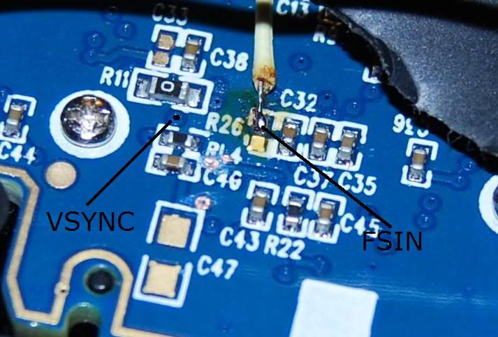
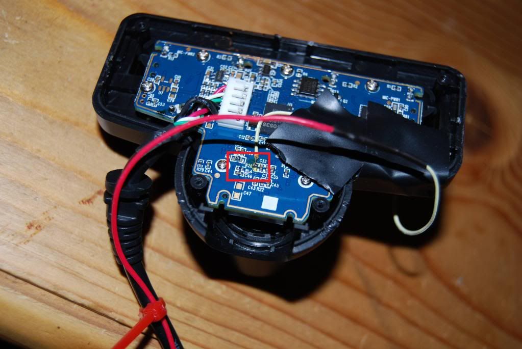
What you can't tell from this picture is how damn small those pieces are. I think this image is about 2cm across. This next picture shows the whole back of the camera.
Do you remember how I told you about my weak soldering skills? Do you remember those ugly joints on the Dynamixel power cord? Right...
Diving In To Electronics
Well, long story short, despite all the evidence that I was going to ruin my camera, I went for it.
I cracked open the camera (literally... it has some one-time plastic snaps holding it together and I had to pry at them until they gave up), unscrewed some stuff, and removed the PCB. Here are video and picture instructions that I found on the process. I got out my trusty $7 soldering iron, a "helping hands" thingy with a magnifying glass, and some bits of wire.
In the end, I did get a wire attached to FSIN on both of my cameras. Somehow I managed to avoid attaching it to the resistor next to FSIN. Somehow I managed to avoid frying any components. On one camera I did pull the little copper contact for FSIN right off of the board... but flooding the exposed depression where the contact pad used to be with solder seemed to reconnect to the invisible wires in the PCB, so it doesn't seem to have mattered. Like the images above, I've used electrical tape to secure the wire to the camera, because a little tug could rip it off (that's how the contact pad was removed the first time). I've been more cautious than these students, as I've wrapped the wire around the case and taped in three places. Now there are lots of shock absorbers that will give before I break the solder connection.
I rebuilt the cameras to the point where they have a nice tilting stand under them again. I left the back panel off so that the wires can escape. In theory I could dremel a little notch in the plastic back to feed the wire through, but I haven't bothered. I had to solder a long wire to the itty-bitty FSIN wire so that it could reach any significant distance. I used speaker wire, since that's what I have long lengths of. Thankfully soldering two wires together isn't that hard. I even put a shrink-wrap cover on them so they look very professional.
Triggering FSIN
Having a wire attached to FSIN doesn't actually accomplish anything unless I can send a signal over the wire. To do that, I returned to Arduino. I told you that thing would come in handy one day.
The FSIN input is apparently a rising-edge triggered signal at 3.3V (all this according to the engineering students referenced above or other online sources). I set up both the left and right camera speaker wire to the same digital output pin on the Arduino. I programmed it to send a square wave on that pin, alternating 0V and 3.3V every 4000us (that's 250 times per second, i.e. double 125 fps). Whenever it goes from 0V to 3.3V it should be triggering a frame capture.
Measuring Frame Rate
When I turned it on I realized that I had no easy way to tell if it was working. So I came up with a wickedly clever plan to test the timing of the camera frames.
I have some small red LED lights in my electronics junk box that have a very fast switching speed, meaning they can turn on and off very fast. Faster than the frame rate of the cameras. In fact, I've found that turning them on and off can be done in under 1000us. Probably much under 1000us, but I don't know for sure. (Note: not all LEDs are fast at turning off. I have another batch of larger LEDs and they would glow for a much longer period of time after the power was removed, making them not useful for my purposes.)
My plan is to flash lights at a high speed, and compare the frames from the two cameras to see if they were both seeing the same step in the light sequence. If so, they would be synchronized (at least within 1000us). I arranged 8 lights in a breadboard that would each turn on, one-at-a-time, for 1000us, then off again, so only one light would be on at a time. Every 8000us (125 times per second) the pattern would repeat. In addition I added more LEDs that would count the number of 8000us cycles in binary. The count should increment once per frame, so you could also call it a frame counter.
All the LEDs were hooked up to my Arduino on digital pins. I am now thankful that I bought the larger Arduino even though I had no plan to use all those connections at the time. I programmed the Arduino to carry out the pattern I just described. With the human eye, the pattern is too fast to see. The 8 sequential LEDs appear to be in a steady half-on state (half-on is interesting because they are only on 1/8th of the time; I suspect that's my brain messing with me). The lower bits of the binary counter also appear steady, perhaps at 3/4 brightness. As you get to the 4-bit of the counter, the switching becomes visible. To test that I had the pattern right, I slowed it down significantly until I could see all the lights operating. Yep, I got it right.
Next I pointed a single camera at the LED array on my desk. Because of the bad lighting, I had to put a 100W incandescent bulb inches above the LEDs to illuminate the scene sufficiently. (Incandescent lamps are rare in my house. I had to steal my wife's make-up light, which led to many days of arguments about the relative merits of make-up and robot hobbies.)
I added a switch to my growing electronics prototype to enable/disable the LED display and another switch to enable/disable the FSIN signal. I started with FSIN disabled and recorded some video of the LEDs.
Something very cool emerged from the 8 sequential LEDs. At first only one of the 8 LEDs was illuminated in the video. That verifies that my LEDs are switching on and off sufficiently fast. It also means that the frame exposure time is under 1000us. But, as I watched the video, which LED was lit gradually shifted over time. For instance, maybe the 3rd LED was lit at first. It would stay lit in every frame for a while, meaning that the frame was being captured in the same 1000us window within the larger 8000us cycle. But, after maybe 1/2 a second, the 3rd light would get dimmer and the 4th light would start to get brighter. After a full second, the 3rd light would be completely dark and the 4th light would be bright. This movement continued through all 8 LEDs, moving from LED to LED approximately once a second.
So what does that mean? I believe that this is proof that my cameras are not actually operating at precisely 125fps. If the Arduino timer is accurate enough (and I've found discussion online that it is), those lights are repeating 125 times per second "exactly". If the camera was also cycling exactly 125 time per second, then the movement from LED to LED wouldn't happen. Doing some rough math, the camera was losing 1000us (the difference between neighboring LEDs) every 1 second (the approximate time it took for one LED to give way to its neighbor). That's 1 part in 1000 slower than 125 fps, so about 0.125 frames per second is being lost, so the camera is actually working at about 124.875 fps. I know it is slower rather than faster because of the direction the LEDs movement was going. If the 3rd LED gave way to the 2nd, the camera would have been going faster. But it wasn't, it was going slower.
While I know this is some pretty amazing research, it gets better. Stay strapped in.
When I switch on the FSIN signal the pattern changes. Instantly, which LED is lit jumps to the 6th LED, regardless of where it was then I switched it on. Maybe the 7th LED is also lit a little bit, so I'm going to say it's at the 6.25 increment in the 8 light cycle. What's more, there is no longer any drift. That 6th LED will stay lit forever, in every frame.
To me, this means that my FSIN signal is working. It is forcing the camera to take its frames at an exact 125 fps tempo, instead of its inaccurate 124.875 fps. Most importantly, the FSIN signal is working to adjust the camera's timing, which would suggest that sending FSIN to both cameras would cause them to be synchronized.
The way I programmed the Arduino, the FSIN signal is sent at the same time that the 1st LED is turned on. That means that the 6th light is lit 5000us after sending the FSIN signal. To me that indicates that there is a 5000us delay in the electronics from the rising edge of FSIN to the actual frame capture. It's possible that this delay is variable based on other camera settings, but I consistently got this value of around 5000us.
[I would like to get a video of this happening. It would require reassembling my LED array, which was reorganized later and no longer works this way.]
Two Camera Frame Rate Testing
Next, I used both cameras at the same time on my desk. Without FSIN, both cameras showed the movement along the 8 LED loop. They didn't drift at the same speed: the second camera showed slightly slower (or faster, I can't remember) movement, and so its actual frame rate was slightly different (and still not 125 fps). This also means that they didn't see the same LED as being lit. The first camera might see LED 3 at the same time that the second camera sees LED 8.
When FSIN was turned on, both cameras immediately saw the 6th LED lit and the drift stopped. Since they both saw the 6th LED lit, the delay between FSIN and the frame was relatively constant between cameras, which is helpful if I am trying to synchronize them. If I turned off FSIN again, the drift resumed, starting from the 6th LED, then the 7th, etc. The different drift speeds meant that over time (roughly tens of seconds) the two cameras would again be seeing different LEDs lit.
Meanwhile, at the ping pong table...
With this success, I returned to the ping pong table. I set up my cameras, my table, blocked out glare from windows, put in my favorite landmarks. This time I also added my LED array. The LEDs were too close together, so I remade my prototype to spread them out, otherwise two LEDs would appear in the same pixel.
This is when things started to go wrong. The new video with FSIN wasn't synchronized. What? Why? How?
I believe that the problem is with lighting. That 100W bulb was needed to illuminate my desk. Once back on the table, I didn't have lights that are equivalently bright. I even have to darken the room somewhat by blocking sunlight that would create glare on the table. I think this causes the required exposure time to exceed the 8000us frame rate.
When it was on my desk, the exposure time was under 1000us because only one of the 8 LEDs was lit in the pictures. Now that they are on the table, they do not behave the same way. More than one is illuminated at a time. To a rough approximation, they are all lit. Even the binary frame counter becomes ambiguous at times -- i.e. it's hard to tell if a light is on or off. Basically the long exposure is smudging the LED status, ruining the crisp results I had been achieving on my desk.
I don't know how the FSIN signal interacts with the camera's natural timing. And I don't know how the exposure time interacts with both of these things. In theory the Linux driver should be able to control exposure time, but in practice I don't believe it works. I believe that the camera is deciding its own exposure time no matter what I tell it to do.
It wouldn't be the end of the world if I had a long exposure time and my LEDs no longer allowed me to see how well it was working. As long as the cameras stay synchronized, I don't think a long exposure time is that big of a deal -- I'd already been taking videos in these lighting conditions and was happy with them. But somehow the (suspected) long exposure time was also messing with the synchronization. Using the ball-bounce method discussed at the top of this post, the two cameras were not synchronized. The FSIN triggers were not interacting well with a long exposure time.
Bottom line, not only could the LEDs not do the job of measuring the frame rate accurately, but the synchronization that had worked so well on my desk was lost.
What Now?
It's been a long time since my last post. Maybe you noticed. I actually did these experiments over maybe 4 weeks, which is why this post is so long (and I left out some details here and there). I have since done nothing for a number of weeks. I am discouraged again, and don't know what to do next.
I think that if I want to make progress, I might have to buy the expensive cameras that I had been considering originally. Maybe a $22 PS3 Eye is insufficient for the level of detail I need to capture. An expensive camera with a big lens on it should capture more light, and therefore allow short exposures again. The expensive cameras also come designed to take an external trigger signal, so I shouldn't have to hack them to make them work.
Of course, now that I've been discouraged for a while, it gets harder to justify spending a stack of cash...
dude... I am making a very very similar application!
ReplyDeleteto disable exposure on the ps2 eye
you have to install v4l2-utils
then use:
$ v4l2-ctl -d /dev/video1 --all
to check all the possible controls
$ v4l2-ctl -d /dev/video1 --set-ctrl auto_exposure=1
to deactivate auto-exposure
$ v4l2-ctl -d /dev/video1 --set-ctrl gain_automatic=0
to deactivate auto gain...
$ v4l2-ctl -d /dev/video1 --set-ctrl exposure=100
to set a fixed exposure!
anyway... I was now reading your article and it is very interesting. I am trying to make a system to track a flying insect (which is as fast as the ball)...
I have 4 cameras on my system and 3 computers, and I am using YARP to distribute the computational power between the 3 computers!
well, now I am going to read your articles since the begining and probably I will have more questions to ask you!
Good Luck!
Hi may I know more about your ways to sync two cameras? Have you used PS3 Eyetoy since then?
DeleteIt might be an idea to look at the raspberry pi camera. There might be a way to synchronize when the images are taken there. You can connect to GPIO pins to give you a 'vsync lock' software would take an image as soon as the vsync lock is released. I don't know how exact the time match would be then.
ReplyDeleteHi may I know more about using a Pi to sync two cameras? Are you talking about taking images with PS3 Eyetoy cameras or Raspberry Pi cameras?
DeleteDear JB
ReplyDeleteI am a Neuroscience PhD student in University College London studying how mice's behaviours influences other mice. I set up an experiment to track mice's location with two PS3 Eyetoy cameras.
To synchronize the cameras when taking the video of the mice, I want to do what you written on the article by wiring the two PS3 eyetoy cameras together but I dont know how to trigger them with an external device. Could you please share with me your way to trigger the cameras with Arduino?
Please feel free to let me know if you have any concern or comment on my research project.
All the best,
Chi-Yu
Hi Chi-Yu,
DeleteDid you find the solution? I work at the university of Edinburgh, and looking for the same solution.
best, Kapil
Sorry I didn't respond when this was relevant to you, @latelykiwi. But for future readers, like @kapil, I dug up the code and have shared it here:
Deletehttps://gist.github.com/jbonyun/6263ccc0e4d9456f5f9807a00aeb00d3
I haven't tested it because I don't have this setup handy. And I made a few edits for clarity, so it's possible I created a typo along the way. Good luck!
Hi @latelykiwi,
ReplyDeleteCheck out this for a write up for use of these cameras for neuro: https://optogeneticsandneuralengineeringcore.gitlab.io/ONECoreSite/projects/PS3EyeCamera/
Hey guys sorry i have not come back to this website for a while. I got some delay to continue this project but now it's the best time! I will let you know if I get anything new.
ReplyDeleteThanks for sharing the code and the website!
Hey, so I busted open the PS3 eye camera and cut the wires in an attempt to shorten the length of the cable. However on connecting it back, all I receive is a black screen output; is there any fix for this?
ReplyDeleteSorry, that's a pretty general symptom. So you opened it up, disconnected the white plastic connector to the PCB, cut those individual wires inside the USB cable to a shorter length, managed to get them back into the white plastic connector, and plugged it back in? I mean, there's nothing that says this shouldn't work theoretically. So either I misunderstand or something went wrong in the execution. Are the wires in the correct order? I see two black wires that would be easy to reverse (in my camera, from top, it's red, white, green, black, black). Are you sure they all conduct properly through the connector? Basically are the connections good? I don't think anyone can properly diagnose "it doesn't work now".
Delete